Graph Schema Builder
PuppyGraph provides a graph schema builder in its web UI. It allows you to create a graph schema interactively, making it easier to visualize and manage your graph structure.
See also Modeling a Graph through the Schema Builder for an end-to-end example of creating a graph schema using the schema builder.
Schema Overview
It is recommended to read this overview to learn more about PuppyGraph's schema definition before creating a schema with the schema builder.
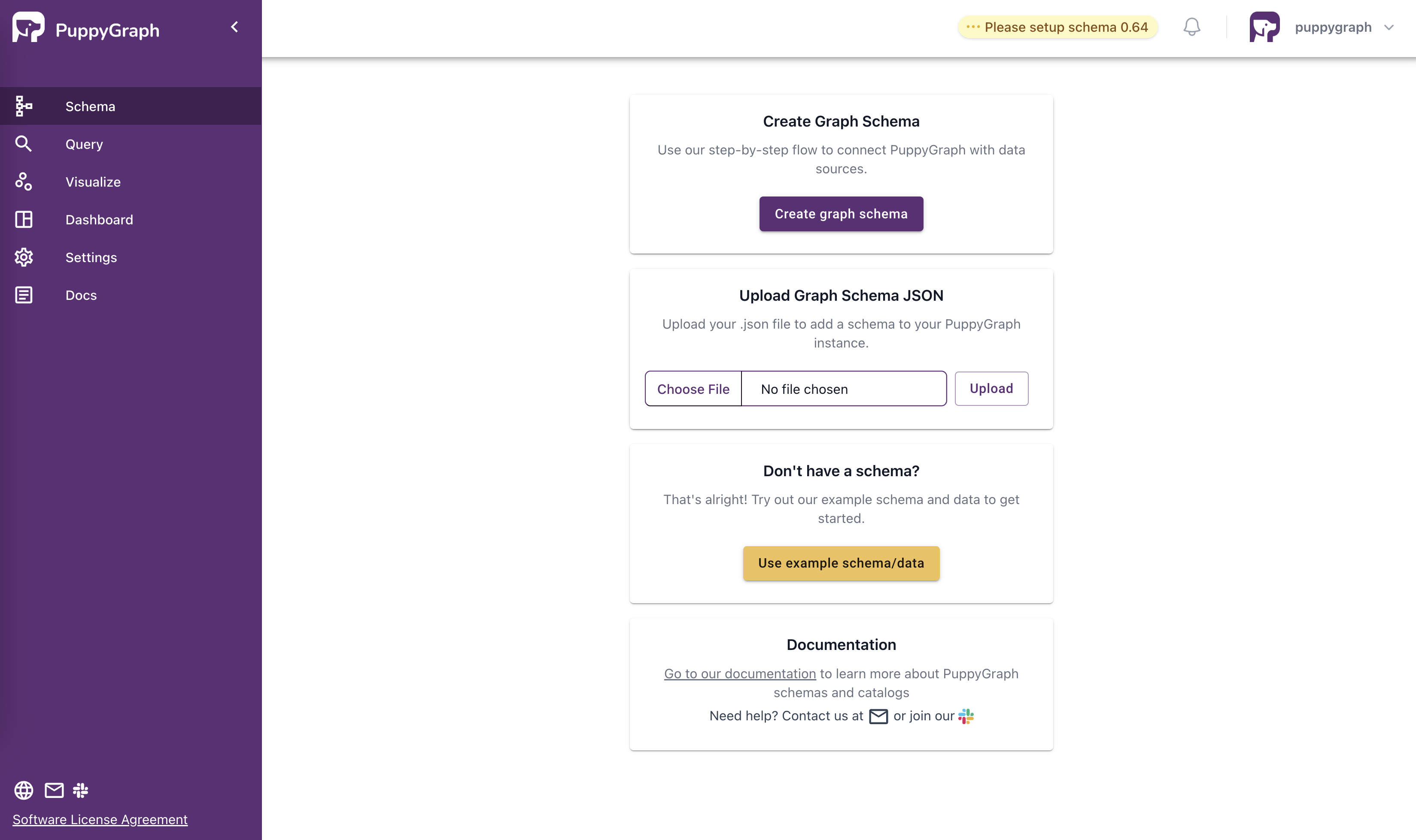
To start, click Create Graph Schema button to launch the builder.
Adding catalogs
Configuring a catalog
Choose the catalog type that matches your data source.
A documentation link for each catalog type is provided at the bottom. Click it to find detailed guidelines on connecting to the data source and completing the configuration.
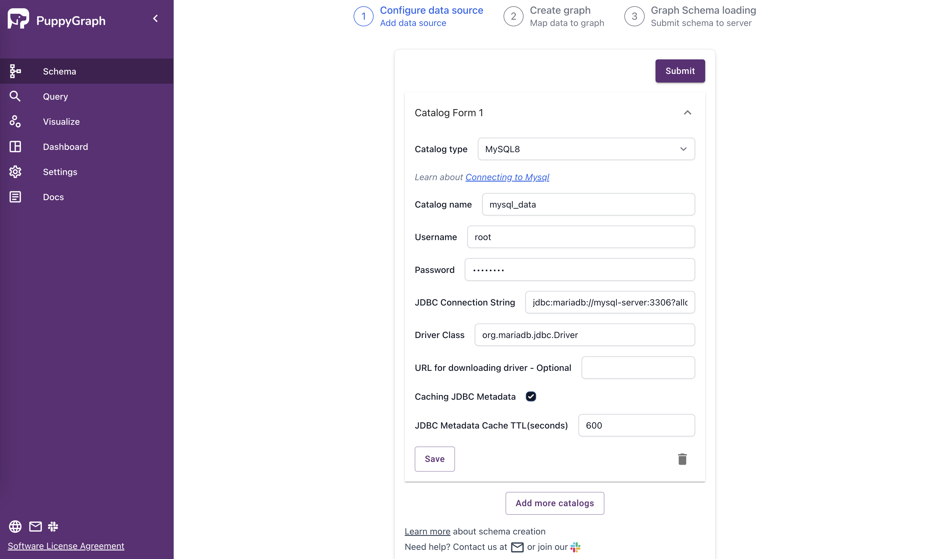
MySQL catalogSave Configuration
After configuring, you need to click the Save button to save the current data source configuration before clicking the Submit button.
Ensure each configuration is correctly saved to avoid losing or making errors in the setup before submitting.
Using environment variables for sensitive information
To avoid hardcoding sensitive information such as passwords, access keys, or tokens in your schema configuration, you can use environment variables. This is especially useful for security best practices and when managing configurations across different environments.
PuppyGraph supports environment variable substitution in catalog configurations using the following format. This format can be used both in the web UI and in JSON schema files:
Where <environment-variable> is the name of the environment variable you want to reference.
Example
Here's an example using environment variables in a catalog configuration:
In this example, ${ENV:DATABRICKS_TOKEN} will use the value of the DATABRICKS_TOKEN environment variable.
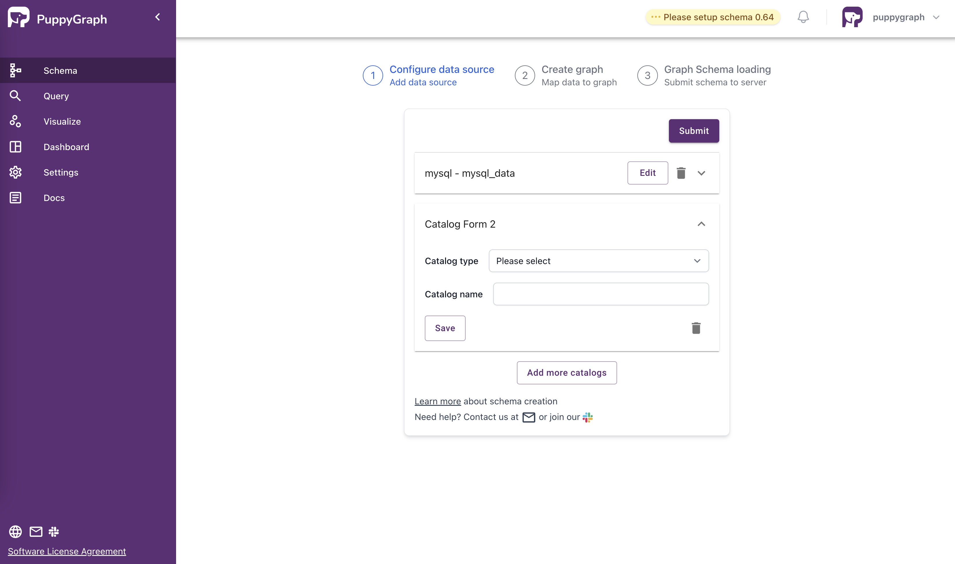
Adding multiple catalogs
If you need to connect to multiple data sources, you can add more Catalog forms by clicking the Add more catalogs button.
Each catalog will be displayed in its own form, allowing separate configuration of different data source connections.
Adding node types
Adding a standard (one-to-one) node type
The Default represents a standard (one-to-one) mapping from a single table to a node (vertex) type.
Moreover, each row in the selected table will be represented as a node (vertex) of the type in the graph.
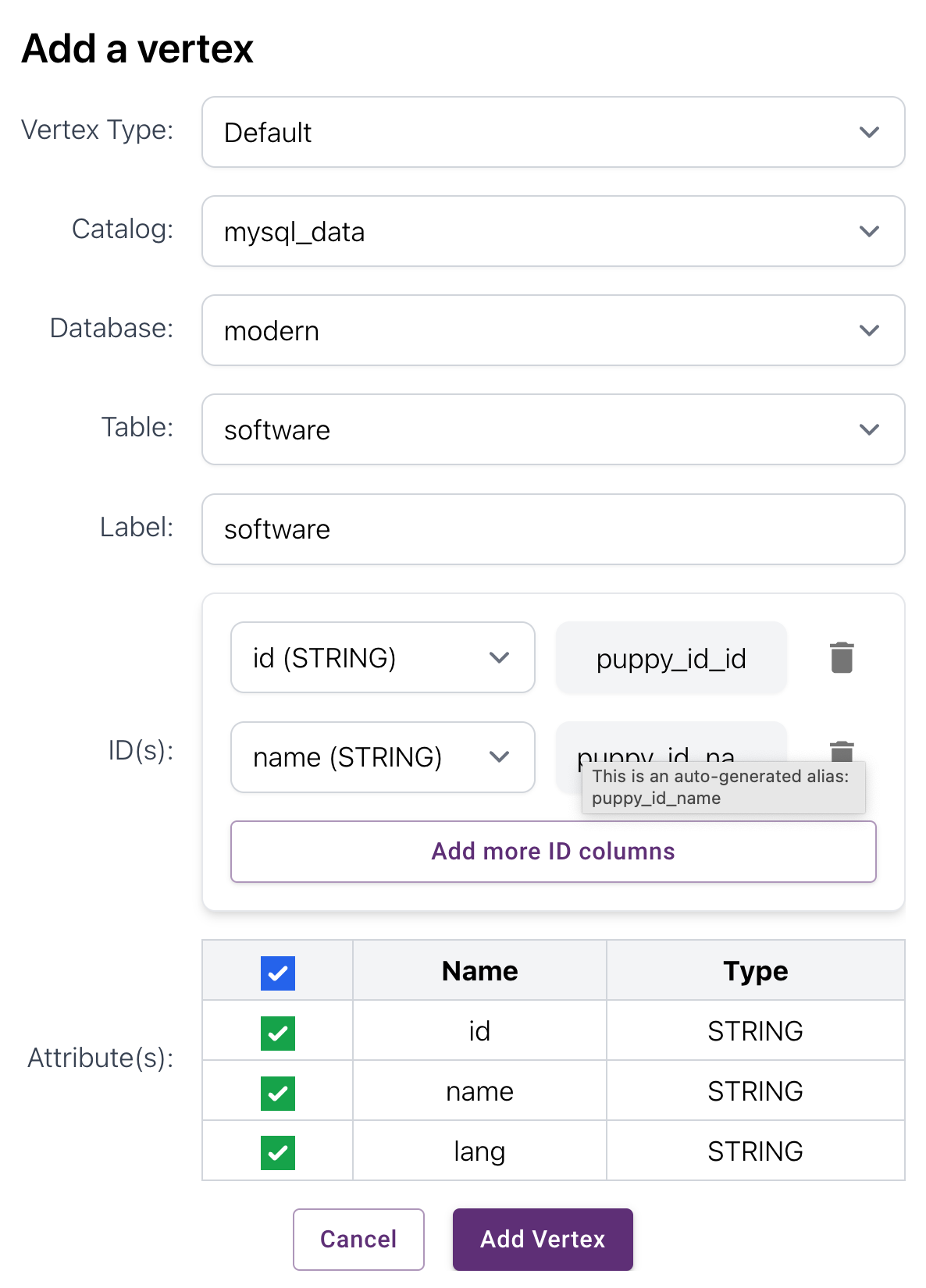
software standard node (vertex) typeThe Node ID uniquely identifies each node (vertex). It can be a single column or a combination of multiple columns from the selected table.
Click Add more columns for adding additional columns to the ID mapping.
- The
ID(s)section lets you select one or more columns to serve as the node (vertex) ID. - When you select a column (e.g.,
idandname), an alias is automatically generated on the right side. The alias will be referred to in the edge type configuration.
For example, if you choose id and name as ID columns, the system will generate aliases like puppy_id_id and puppy_id_name to prevent conflicts and ensure clarity in ID references.
Next, you can define attributes for the node (vertex) type. In the screenshot, columns like id, name, and lang are mapped as attributes and will be stored as part of the node (vertex) type.
- Each attribute column has a checkbox next to it, allowing you to enable or disable it.
- There is a
Select Allcheckbox at the top, which allows you to quickly include or exclude all attributes at once.
Click the Add Vertex button to complete the creation of the node (vertex) type.
Adding a flexible (many-to-one) node type
In some cases, a node (vertex) type may not have a dedicated table. But it can be derived from one or more tables, where each table may contain multiple occurrences of a single node (vertex) value.
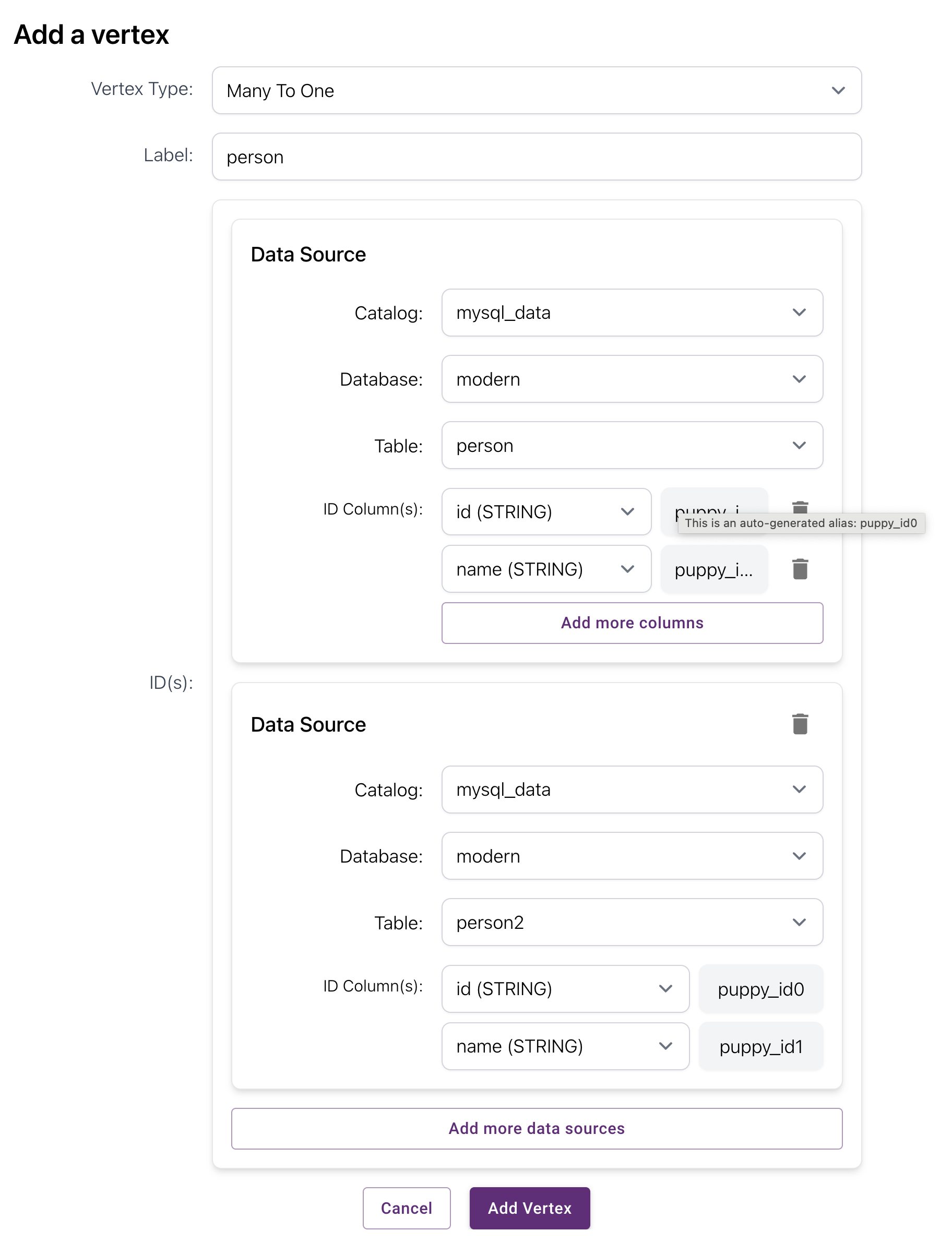
person flexible node (vertex) typeYou can add multiple tables for the same node (vertex) type by clicking the Add more data sources button. There are two data sources: person and person2 in the screenshot as an example.
The first data source decides on the number and type of ID columns, and all subsequent data sources must match in type and order. For example, if the first source has id and name as ID columns, others must also have two matching columns with the same type.
A flexible node (vertex) type cannot contain attributes. It is recommended to create a normalized table and map it to a standard node (vertex) type if you need attributes. Alternatively, you can create a flexible node (vertex) type and add attributes to the edge type that connects to it.
Adding edge types
Configuring the identifier
Similarly, you first configure the identifier for the edge. This is important for uniquely identifying each edge in the graph.
- Similar to node (vertex) ID configuration, you can choose multiple columns for the ID.
- You can also choose not to specify an ID, which would create an edge using a unique identifier generated by PuppyGraph. This method might have performance implications, as it would require PuppyGraph to generate a unique ID for each edge at runtime.
Configuring linked node types
The next step is to choose the type of From Node and To Node for the edge type.
- From Node: This defines the starting point of the edge. In the example, it's set to
person, and you'll be selecting ID columns that belong to thepersonnode (vertex). - To Node: This defines the ending point of the edge. In the example, it's set to
software, and you’ll select ID columns related to thesoftwarenode (vertex).
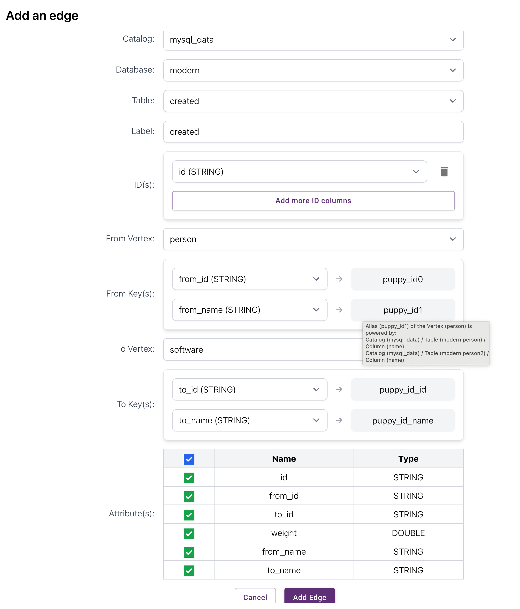
created edge typeFor both selected node (vertex) types (From and To), you need to select the columns that match the ID columns of the respective node (vertex) types. This is similar to how you configure foreign keys in a relational database.
The edge configuration will only allow you to select ID columns that have the same type as those of the corresponding nodes (vertices). For instance, if the ID type for person is STRING, the selection box for the From Node will only allow you to select ID columns of type STRING. This ensures that the edge is properly mapped to the correct ID columns of both the source and target nodes (vertices).
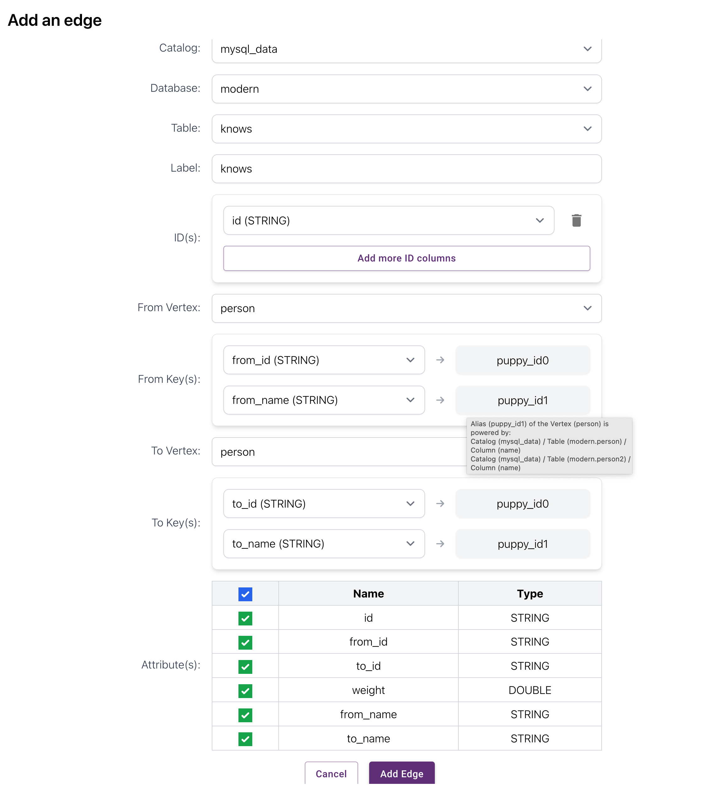
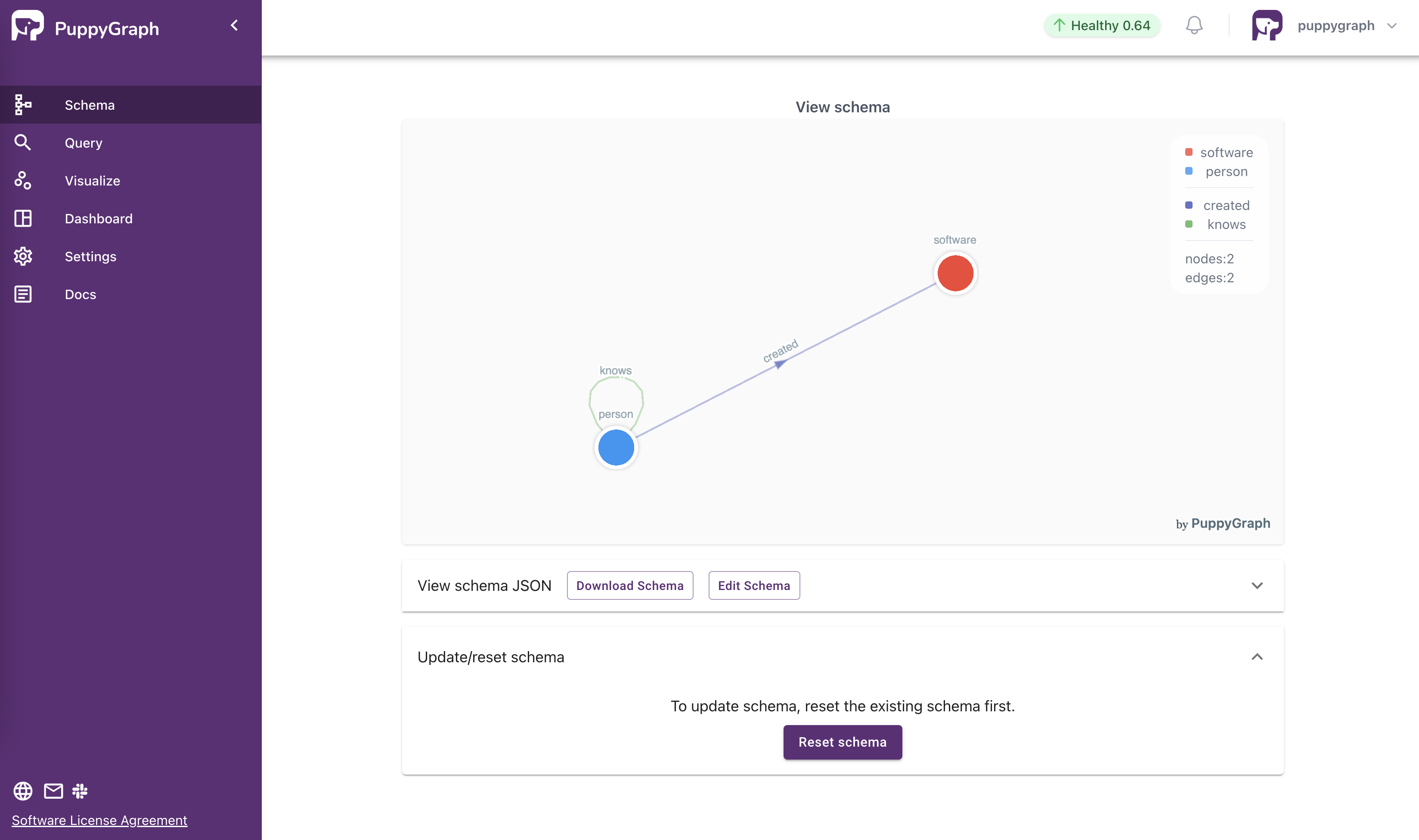
knows edge typeSubmitting the schema
The schema builder visualizes the node (vertex) and edge types you have added to the graph schema.
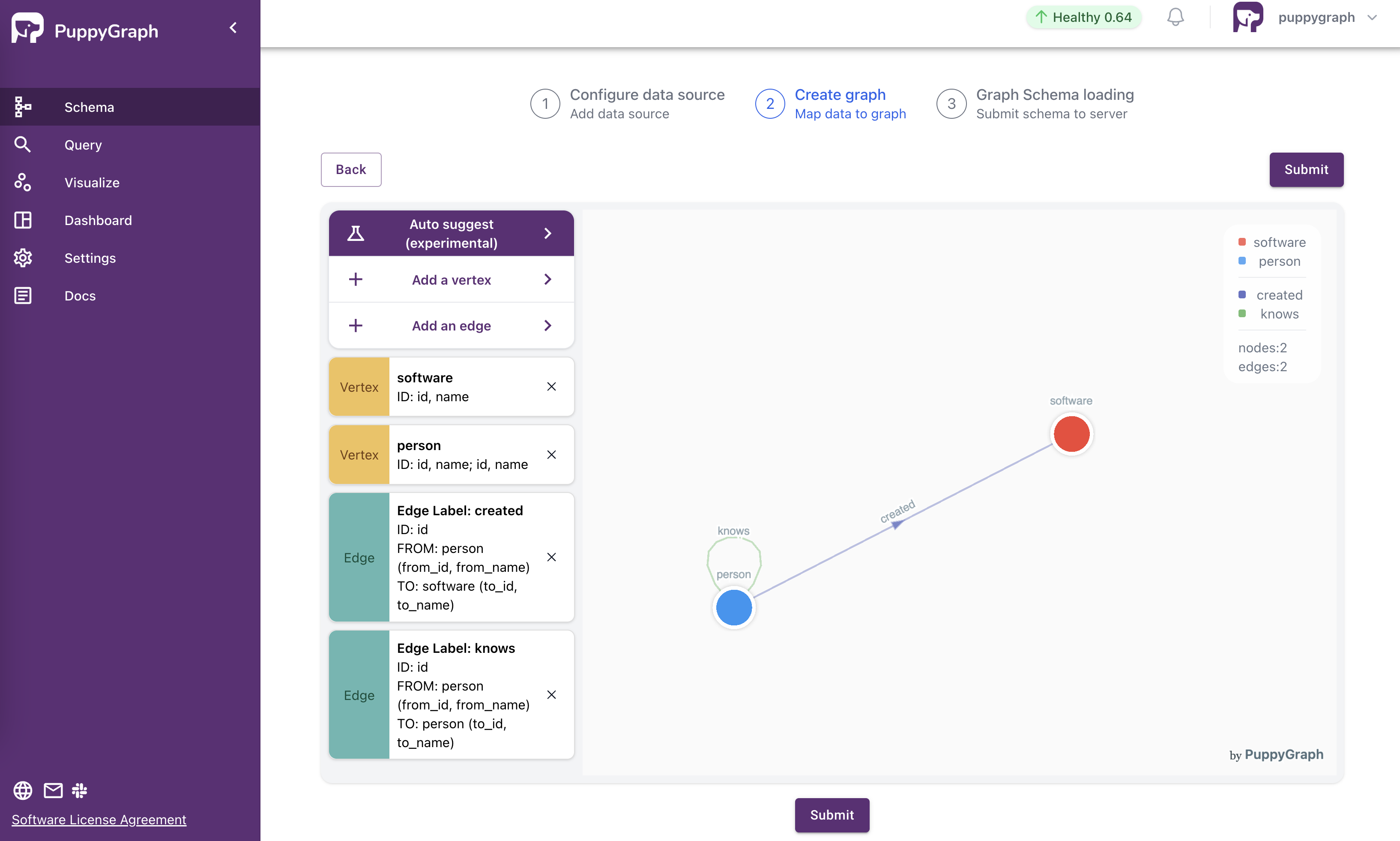
If everything looks good, click Submit to initialize the graph with the finalized schema.